Sum of od in total cross sectional areas of all cables.
Cable tray support design calculation.
A 50 fill ratio should equal the maximum number of cables pulled in a given cross section.
On tue dec 2 2014 at 7 52 pm electrical notes articles wrote.
6 cable ladder and cable tray systems including channel support systems and other associated supports definitions and abbreviations accessory component used for a supplementary function e g.
Calculate cable tray width calculate cable tray area calculate cable tray length calculate cable tray weight calculate remaining width of cable tray calculate remaining area of cable tray free download.
Total sum of the diameters.
Straight section supports installed at 5 foot 1 5m centers are typical.
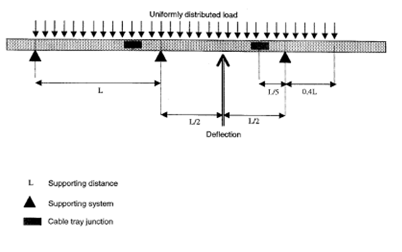
Support load calculation per iec 61537.
One or more spans iec 61537 7 3i for installations with more than one span it is important to notice that the loading capacity is not the same form one end to the other.
Cable raceway tray support calculations cable tray is sized based on the number and type of cables required for the current and future need.
Cable tray systems design shall comply with nec article 392 nema ve 1 and nema fg 1 and follow safe work practices as described in nfpa 70e.
For cable tray installers this publication is intended as a practical guide for the proper installation of cable tray systems.
Evenly distributed load 2 x point load support distance.
3 use the pull down menu to choose the type of cables being used and answer any of the pop up questions.
The installation will use cat cable at 19 in diameter 20 lb.
A cable tray manufacturer has to provide the cable tray parts data as width height weight.
It would take 7 3 inch conduits to obtain this allowable fill area 7 2 95 square inches 20 65 square inches.
Steel fiberglass or else to state the right diameter.
The cost of 600 volt insulated multiconductor cables listed for use in cable tray is greater than the cost of 600 volt insulated individual conductors used in conduit.
1 insure that macros have been enabled.
Then according to cable tray support configuration a structural engineer may calculate the actual load on each support rod and according to rod material.
Tray design depth.