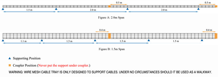
The length between support positions will change depending on the cable design size materials and weight.
Cable tray support distance.
The cable tray institute cti was founded in 1991 to support the cable tray industry by engaging in research development education and the dissemination of information designed to promote enhance and increase the visibility of the industry.
Trays that meet nema specs support 3 4 5 or 6 inch fills and widths from 6 to 36 inches.
There are cable trays available to meet all nema requirements with spans of 8 12 16 or 20 feet and loading capacities of 50 75 or 100 lbs ft.
Metallic cable tray system.
The label ensures that the service entrance conductors can be traced throughout the cable tray.
The nema classes are based on cable loads of 50 75 and 100 per lineal foot.
Support load calculation per iec 61537.
Cable trays shall be supported by mild steel galvanized brackets at regular intervals of 1 2mm maximum and at 255mm from bends and tees.
See the actual nec text at nfpa org for the complete code section.
An assembly of cable tray straight section fitting and accessories that forms a.
For example an mdpe sheathed cable will be stiffer and therefor require a greater distance between supports than the same lsoh cable to achieve the same 2 deflection sag.
Evenly distributed load 2 x point load support distance.
Longer spans mean fewer supports which translates to lower installed costs.
A cable tray fitting which changes the direction in the same plane.
To join two components together clamp or fix to walls ceilings or other supports covers and cable retainers associated supports bespoke supports for cable tray and cable ladder other than bs 6946 channel.
Mushroom headed steel roofing bolts and nuts shall be used for the installation and coupling of trays.
A cable tray fitting which is suitable for joining cable trays in three directions at 90 degree intervals in the same plane.
This classification is based on the working load the total weight of the cables and the support span the distance between supports.
One or more spans iec 61537 7 3i for installations with more than one span it is important to notice that the loading capacity is not the same form one end to the other.
Below is a preview of the nec.
6 cable ladder and cable tray systems including channel support systems and other associated supports definitions and abbreviations accessory component used for a supplementary function e g.
A generic guideline developed by the cable tray institute indicates that cable trays should not be filled in excess of 40 50 of the inside area of the tray or of the tray s maximum weight based on the cable tray specifications.